Technology
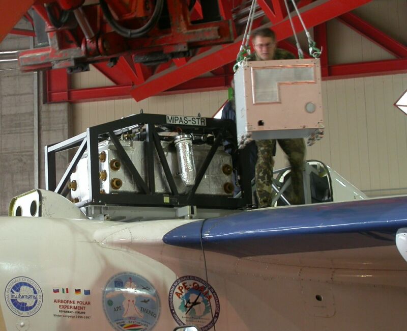 |
The geophysica dorsal bay compartment with MIPAS-STR optics during installation of the electronics module. (240k)
|
General
The MIPAS-STR (Michelson Interferometer for Passive Atmospheric Sounding on STRatospheric aircraft) is a cryogenically cooled FTS. The entire optics is operated at dryice temperature with the exception of the detector, which is cooled to 4K. The system makes use of proven subsystems from the previous MIPAS-FT ("Flugzeug" Transall) and the MIPAS-B2 (balloon).
New features are fully automated operation, time-equidistant sampling, compact arrangement with low budget of mass and size, pointing mirror integrated in the cooled area, improved telescope, in-flight cooling and stable thermal arrangement using aluminum for frame and mirrors.
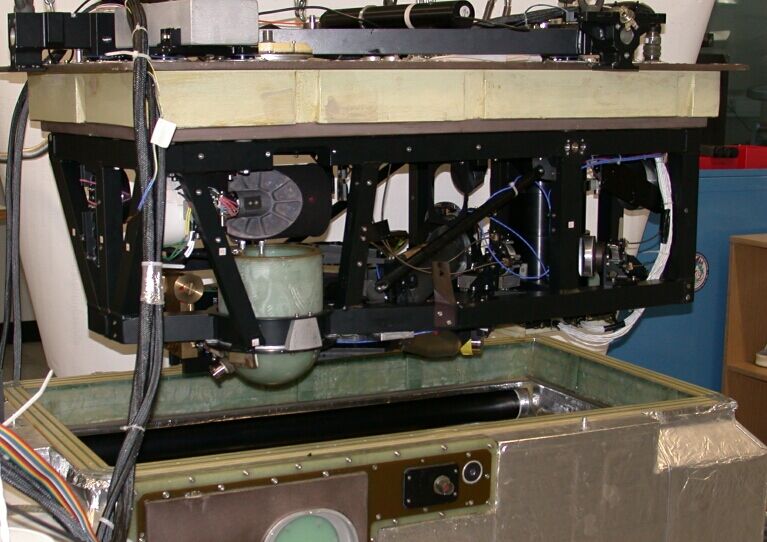 The optical sensor above its cooling device. (80k) |
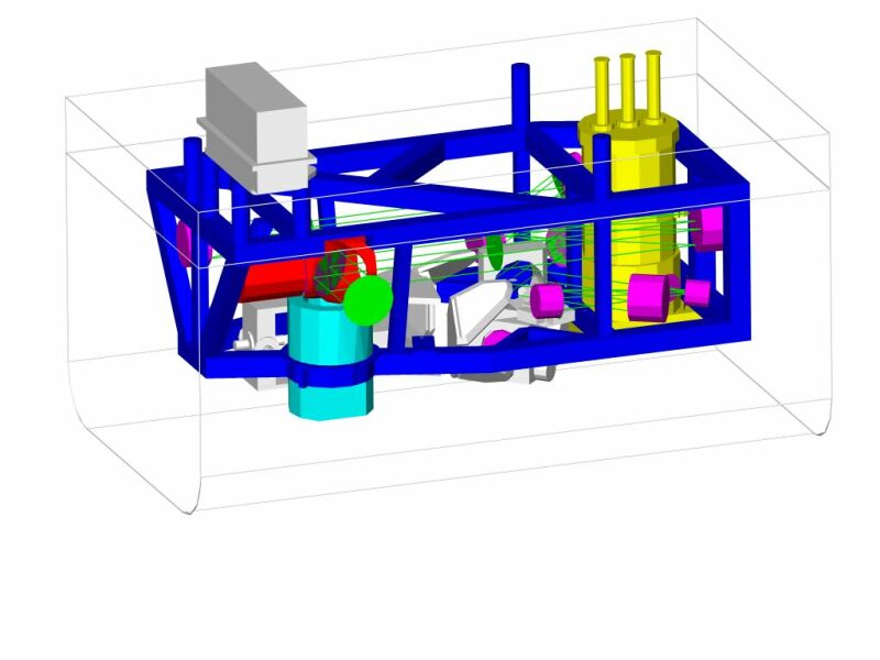 CAD-drawing of the frame with the optical subsystems. (64k) |
Characteristic instrument data
| Line of sight stability Entrance beam diameter |
1 arcmin (3s) 82 mm |
| Spectral resolution (2-sided) Optical path difference (unapodized) Beam diameter inside DPI Etendue Field of view, FOV Scan velocity |
0.034 cm-1 ±15 cm 50 mm 2.6 x 10⁻³ cm2 sr 0.44° (26.4', full cone) 3 cm/s |
| Detector type (area) Signal frequencies |
Si:As - BIB (1.6 x 1.6 mm2) 2.3 – 5.8 kHz |
| Noise equivalent spectral radiance (NESR): - Channel 1: 770 - 1000 cm-1 (10.0 - 13.0 mm) - Channel 2: 1200 - 1370 cm -1 (7.3 - 8.3 mm) - Channel 3: 1585 - 1645 cm -1 (6.1 - 6.3 mm) - Channel 4: 1845 - 1940 cm -1 (5.2 - 5.4 mm) |
[W/(cm2 sr cm-1)] 7 x 10⁻⁹ 5 x 10⁻⁹ 4 x 10⁻⁹ 7 x 10⁻⁹ |
| Temperature and emissivity of blackbodies - BB1 inside the optic module: - BB2 in the upper isolation of the optics module: Accuracy of calibration |
200 K, 0.997 (cavity) appr. 240 K (floating), 0.98 (flat) 1-3 % |
| Sampling frequency (time-equidistant) Sampling frequency (interpolated to equidistant sampling positions) Data rate (4 channels incl. housekeeping data) |
48.8 kHz (50 MHz / 1024) 47.4 kHz 50 - 170 kB/s |
| Refill intervals of cryogenics (lHe, lN2,dry-ice) Electrical power (at voltage) Weight (optic module & electronic) |
24 hrs. 300 W (28 VDC) 200 kg (150 kg + 50 kg) |
Main Components of the instrument
Pointing system:MIPAS-STR measures spectra with different elevation angles (the yellow ranges) in limb sounding mode (-4° < h < 10°) and in deep space mode (h = 90°) (see basics) .The elevation angles are stabilised to correct for roll-angle movements of the aircraft. Therefore the scan mirror is continuously adjusted based on the data measured by the instrument-fixed AHRS (Attitude and Heading Reference System). |
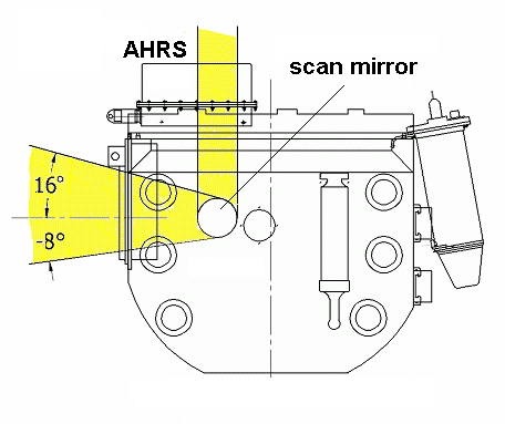 Scan range of the pointing system. (71k) |
Optical System :Linear representation of the ray propagation through MIPAS-STR. Infrared radiation, selected by the pointing mirror enters the interferometer via a 3-mirror telescope. After passing the interferometer the radiation is detected by 4 LHe cooled Si:As detectors. The instrument field of view (FOV) is defined by the LHe cooled stops FS3 and AS3. The stops AS1, FS1 and the shields suppress radiation from outside the FOV and most of the radiation which is scattered inside the front-optics. The radiation which is diffracted at these stops (primarily originating from the "hot" source earth) is shielded by the Lyot- and the FS2 stops. |
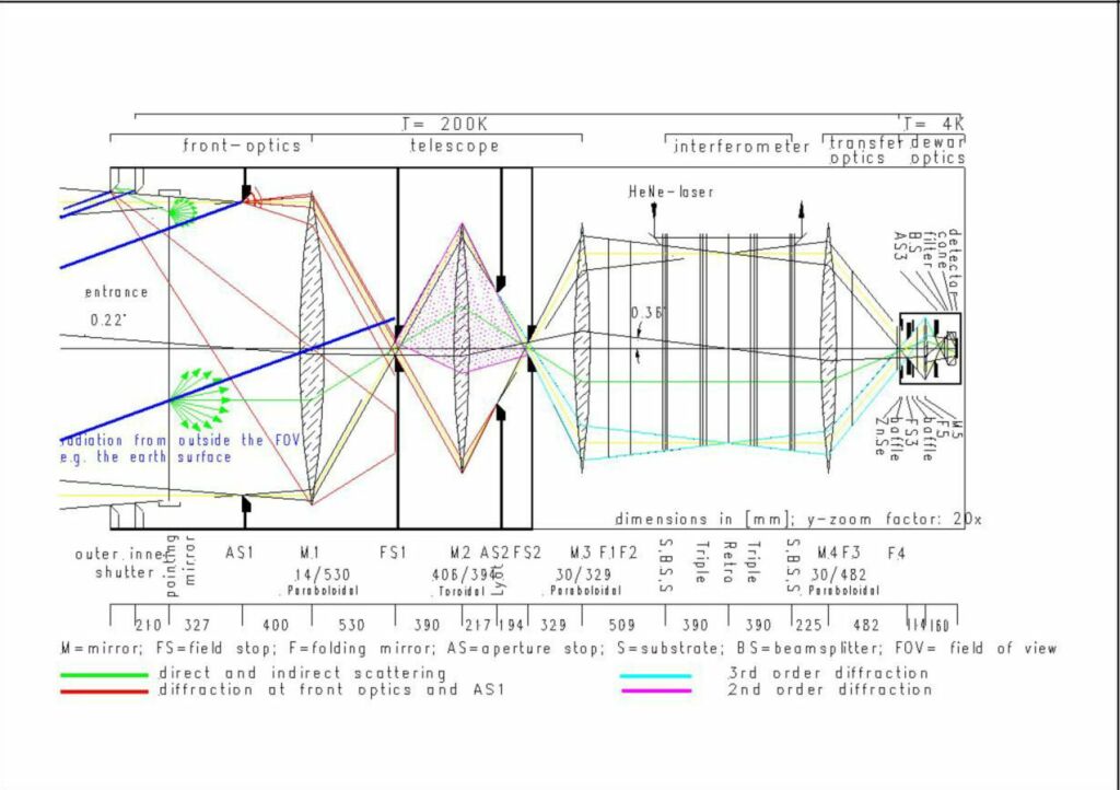 Linear representation of the optic. (92k) |
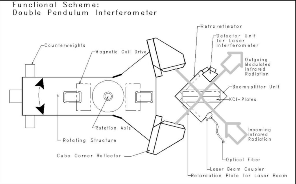
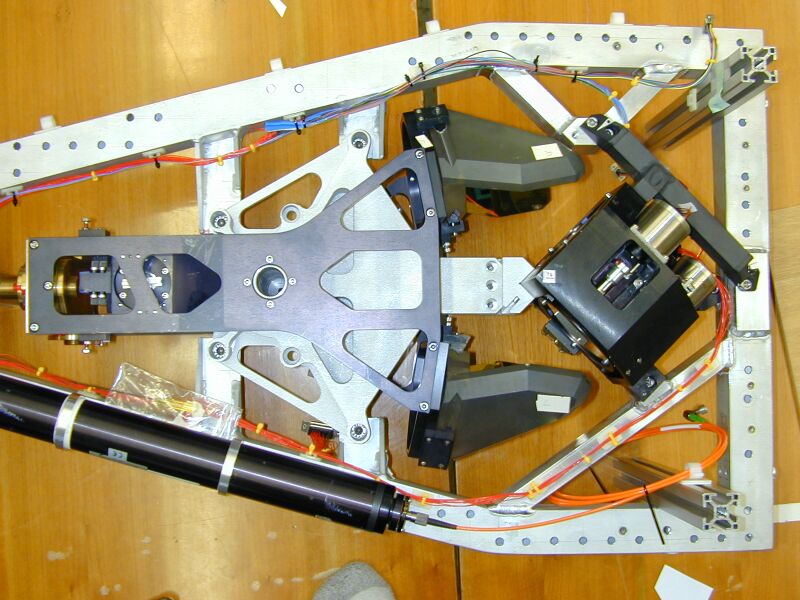
Double pendulum interferometer (DPI):The interferometer is of the double pendulum type tailored for the rough aircraft environment with equidistant sampling in the time domain. Inside the DPI the radiation is divided into two parts at the beamsplitter BS. Each of the beams is then successively reflected at the three surfaces of a triple mirror, the retroreflector and again at the triple mirror before being recombined at the beamsplitter. |
|
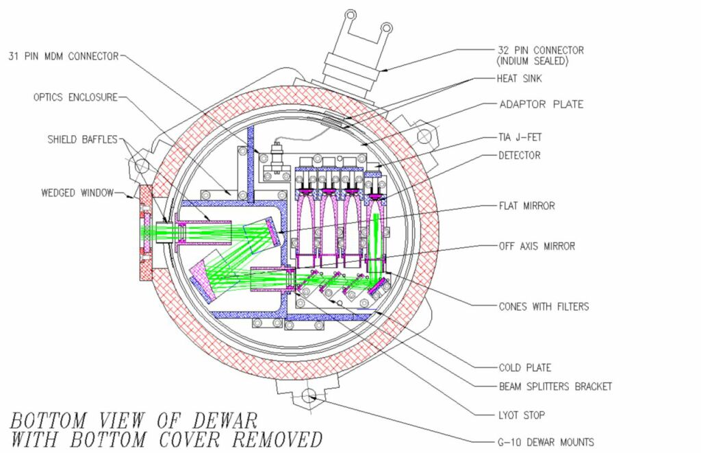
Detector unit:The focal plane with dichroic beam splitters, optical filters, Si:As detectors is cooled to 4 K by liquid helium. Two stops (field and aperture stop) define the acceptance angle and the aperture of the instrument, respectively. After separation by the dichroics the radiation is guided onto the detector elements by adapted Winston cones. The division into 4 channels is necessary for NESR improvement as well as for efficient data reduction. |
|
Cooling device:In order to reduce the background radiation and improve NESR, the optic module is cooled to 200 K. The cooling system consists of 10 inter-connected tubes integrated in the polyurethane (PUR) foam structure of the insulation tub. The tubes are filled with max. 20 kg of dry ice. The pressure inside the tubes is kept at 1000 hPa during flight. The tub protects the optics against humidity and dust, pressure equalization is made via a desicater. For measurements, two shutters (one in the tub, one in the aircraft cowling) are opened above the tropopause. |
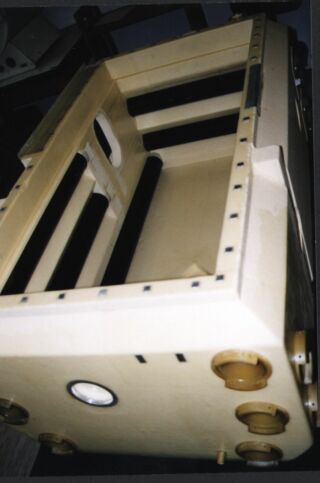 The cooling compartment. (20k) |
Mechanical aircraft interface:The main requirement of the attachment of MIPAS on the back of M55 is to minimize the influences of a/c vibrations to the sensitive optics. Therefore a mounting frame was designed by using FE-Analysis with the goal to avoid eigenfrequencies lower than 100 Hz. Other design drivers were low mass, areas of access, and safety regulations. The result is a truss construction built up of welded aluminum profiles. |
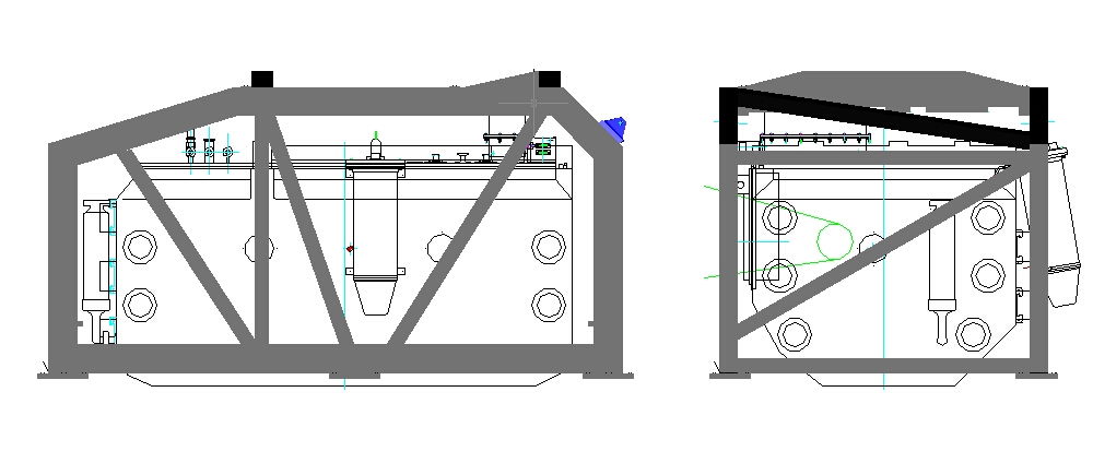 Sketch of the mechanical interface. (100k) |
Electronics:The on-board computer platform is a ruggedized, single-slot PC with standard interfaces as Ethernet, SCSI, RS232/RS485 and VME-Bus. The operating system and user software are running from FlashDisk and data are recorded on Flashdisk as well. A transputer network connects the PC with the subsystems: interferometer electronics, line-of-sight-electronics, housekeeping and auxiliary electronics. A integrated watchdog controls OS and user SW and forces a restart on failure. |
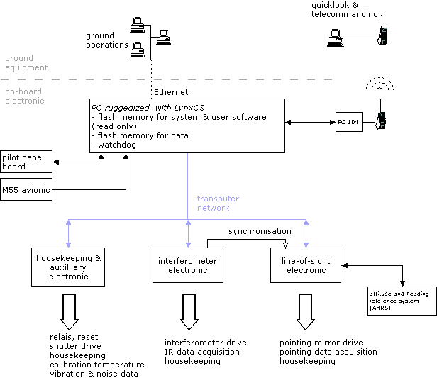 Schematic view of the onboard electronic. (54k) |
On-board software structure:Main feature is the fully automatic operation. A system of parallel user processes communicates with the transputer network, drive external PC connections, runs data acquisitons and controls the independent subsystems with self-repairing mechanisms. Operating system is the very reliable Realtime Unix LynxOS. |
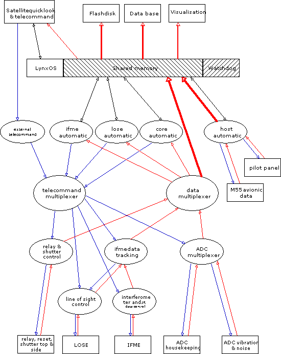 The structure of the onboard software. (30k) |
Iridium satellite link:For online-control of the instrument a up- and downlink connection from a ground unit to the onboard computer is installed. Therefore two standard Motorola 9505 cell phones are used in the data transfer mode of the Iridium system, consisting of 66 polar orbiting satellites. The data rate is approx. 300 Bytes/sec. |
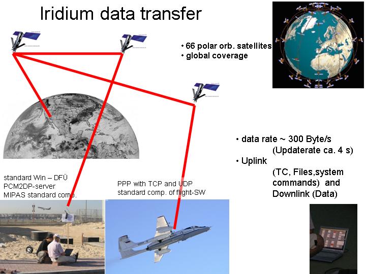 Instrument control and data link via Iridium satellite link. (63k) |

